
The magnetic field strength of the FONAR UPRIGHT® Multi-Position™ MRI is 0.6 Tesla. At 0.6 Tesla, it is categorized as a “Mid-Field” MRI. Most “Open” MRIs (all of them recumbent-only scanners) operate at 0.3 Tesla.
Many equate magnetic field strength to image quality – the higher the field, the better the image. All other things being equal, that is a fair statement. In fact, however, all other things are not equal, meaning that in comparing one MRI to another, field strength is only half of the story.
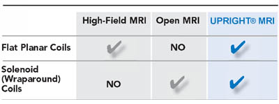
The magnetic configuration of the UPRIGHT® MRI is dramatically different from all other MRIs, both High-Field MRIs and so-called “Open” MRIs. As a result, the UPRIGHT® MRI is able to use both solenoid and planar RF receiver coils. No other MRI can do this.
This explains why the UPRIGHT® MRI’s 0.6 Tesla images are competitive with 1.5 Tesla High-Field MRI images. Here is the explanation of why the magnet configuration of the UPRIGHT® MRI is advantageous:
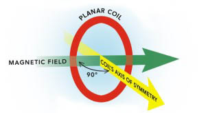
A Fundamental Principle of MRI:
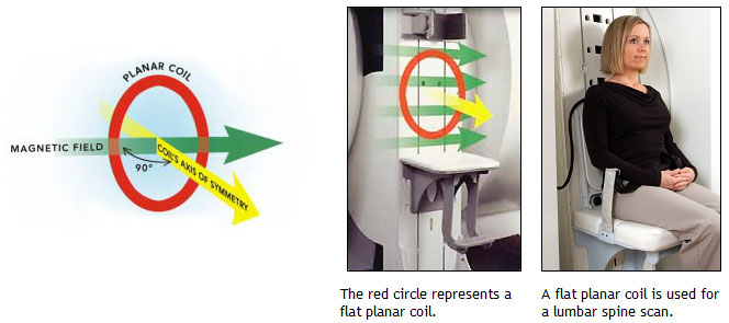
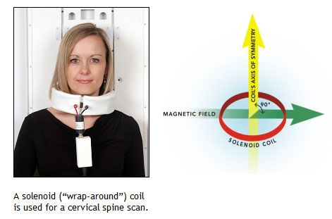
The RF receiver coil achieves maximum sensitivity when its axis of symmetry (yellow arrow) is perpendicular (90) to the direction of the magnetic field (green arrows).
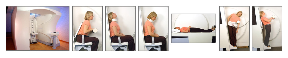
The UPRIGHT® MRI has a unique magnet design, which allows it to employ this principle in two ways. The patient is positioned between two vertical poles so that the magnetic field transverses the body in the left-right direction (green arrows) This unique design allows both flat planar and solenoid (“wrap- around”) coils to be used separately or in combination (in quadrature).
The UPRIGHT® MRI Can Use Solenoid (“Wrap-Around") Coils (which High-Field MRIs can’t):
| UNIQUE APPLICATIONS | Rotates patients from recumbent to upright |
| Comparative scans in both Upright and Recumbent positions | |
| Flexion, Extension, Standing, Sitting and Lateral Bending positions | |
| Scans patients in their position of symptoms | |
| Ideal for anxious and claustrophobic patients | |
| The only choice for patients that cannot lie down | |
| MAGNET | |
| Field Strength | 0.6 Tesla |
| Magnet Type | Iron-frame Electromagnet |
| Cooling System Type | Water (closed-loop); No Cryogens |
| Field Orientation | Horizontal, transverse to the patient |
| Configuration | Front-Open and Top-Open |
| Patient Gap Dimensions | 18 inches (46cm) pole-to-pole |
| Patient Comfort | Upright/Sitting patient faces out and can watch a large flat-screen TV with an unobstructed view |
| PATIENT BED | |
| Positioning Capabilities | Translate, Elevate & Angulate |
| Rotates patient from recumbent to upright | |
| Patient Stabilization | Table tilts backward at 7 degrees to reduce patient motion |
| Patient immobilization fixtures | |
| VersaRest™ trans-polar stabilization bars | |
| RF Receiver Coil Placement | RF coils mount easily to movable fixtures |
| Patient Weight Limit | 500 lbs. |
| RADIOFREQUENCY SYSTEM | |
| Transmitter Configuration | Dedicated, Circularly Polarized, Planar |
| Receiver Configuration | Dual-channel |
| RF RECEIVER COILS (Standard Coil Package) |
|
| Solenoid/Linear | High-Performance Spine & Body Wide Belts (45", 55", 65") |
| Flexible Cervical | |
| Signal-Plus Universal Coils | |
| Solenoid Wrist | |
| RF RECEIVER COILS (Advanced Coil Package) |
|
| Planar | Quadrature Planar Coil and fixture |
| [Note that the Upright MRI is dramatically different than an Open MRI as if utilizes planar (flat) coils to image the spine, just like a high-field MRI] | |
| Quadrature | Quadrature Head Coil |
| Quadrature T-L (Thoracic-Lumbar) Coil | |
| Quadrature Knee Coil | |
| Phased Array | Shoulder (with Immobilization Fixture) |
| GRADIENT SYSTEM | Bi-planar self-shielding |
| Type | Bi-planar self-shielding |
| Maximum Strength (mT/m) | 20 |
| Slew Rate (T/m/s) | 33 |
| Minimum Slice Thickness | 2.0 mm (2DFT) |
| 0.8 mm (3DFT) | |
| Minimum Field-of-View | 6.0 cm |
| IMAGING TECHNIQUES | |
| Pulse Sequences | Spin Echo (SE) |
| Multi-echo spin echo (MSE) | |
| Dual bandwidth Double-echo (DE) | |
| Fast Spin Echo (FSE) | |
| Inversion Recovery Spin Echo (IRSE) | |
| Inversion Recovery FSE (IRFSE): STIR, FLAIR | |
| Driven Equilibrium FSE (DEFSE) | |
| Driven Equilibrium IRFSE (DEIRFSE) | |
| Single-shot FSE (SSFSE) | |
Gradient Echo (GRE): |
|
| MR Angiography: 2D-TOF and 3-D-TOF Ramped RF |
|
| SEQUENCE CONTROLS | |
| Fast Spin Echo | Driven Equilibrium |
| Echo Train Length, Echo Offset, Echo Spacing | |
| Gradient Echo | Flip Angle |
| Steady-State, RF Spoiling, Rephased | |
| Magnetization transfer (MT) | |
| Direction of flow saturation | |
| Scan orientations | Multi-Angle Oblique (MAO™), Dual-Axis Oblique |
| Preparation Pulses | Presaturation pulses |
| Magnetization transfer (MT) | |
| Frequency Selective Saturation (e.g. fat, water, silicone) | |
| Diffusion-Weighted (DWI) | |
| Trigger/Timing | Test Bolus |
| Breathhold, Fluorscopic | |
| Reconstruction | Fast Fourier Transform (DFT): 2DFT, 3DFT |
| Partial (Half) Fourier | |
| ZIP interpolation | |
| 2-point Dixon, 3-point Dixon for Fat Suppression | |
| Firing Order | Cross-talk minimization |
| Interleaved | |
| Interleaved by Subscan (e.g. breathhold) | |
| Sequential | |
| Data Acquisition | Rectangular FOV (continuously variable phase sampling ratio) |
| Multiple Sub-Scanning | |
| Centric Phase Encoding | |
| Flow Compensation, Ramped RF | |
| Low Bandwidth, Multi-bandwidth | |
| Continuously Variable Display Matrix | |
| Swap Frequency and Phase | |
| Repeat and Replace Slices | |
| Continuous Scan Mode, Breath-hold Imaging, Kinematic Mode | |
| Prescan Indicators | Relative resolution |
| Absolute resolution (frequency and phase) | |
| Post-Processing | MIP with rotate, tumble, pan |
| Image enhancement | |
| Bright Balance™ | |
| Display and Analysis | Windowing, ROI, zoom, pan |
| Cursors, profiles, derivatives, mean, standard deviation | |
| Image subtraction | |
| SNR measurements | |
| Image Viewing Software (IVS) for referring physiciand to view their patients' scans on a CD | |